4 Myths About Air Valve Design and Performance
There are many myths regarding Air Valve design and performance. Four of the most popular ones are:
Myth 1 – An Air Valve Is an Air Valve is an Air Valve………….
In a recent discussion on Air Valve performance with a senior design engineer from a prominent Consulting Engineering firm, he casually mentioned that an Air Valve is just and air valve as they all operate similarly.
The reality is that Air Valves have over the past 100 years or more, evolved into four major designs each with their own unique performance characteristics. In addition, each design has spurred many variations and adaptations. More importantly, empirical research indicates that Air Valves of the same design type and even of a similar shape, may perform differently under the same operating conditions.
It is therefore imperative that the design engineer distinguishes between the different Air Valve design types and their derivatives and carefully evaluates the performance characteristics of each to a select a design most appropriate for his/her application.
An Air Valve is not just an air valve. The correct design type selected appropriately for the application will contribute immensely to the efficient operation of a pipeline and the reduction in maintenance costs. The incorrect design and/or the incorrect application of the air valve can contribute directly and indirectly to several operation and maintenance issues.
Myth 2 – Manufacturers’ Published Data can be accepted at face value
The 1st myth segues into the 2nd myth. A design engineer is heavily reliant on the published data of the Air Valve manufacturer. However, tests conducted specifically over the past 10 years by both manufacturers and universities have indicated major discrepancies between actual performance testing and manufacturers published data.
The problem with most manufacturers published data lies in the cost of testing Air Valve performance. Air Valve performance testing is a very expensive undertaking, and few manufacturers or 3rd Party test facilities have the capacity to undertake Air Valve testing, specifically for vacuum function, in sizes larger than DN80.
Some manufacturers who have conducted testing, have due to cost and/or equipment constraints only conducted testing on one or two of the smallest valves sizes in their range or, only conducted discharge testing and not air intake testing.
This results, in the case of manufacturers who have conducted partial testing, extrapolating the results of the smaller sized valves for the larger sized ones. This may sound like a reasonable practice but, the extrapolated results often do not take into account the complexity of scaling for Air Valves due to the many variables such as flow paths, the positioning of the floats etc.
For the vast majority of Air Valve manufacturers, their published data is purely theoretical and, often based on utilizing one of two well-known formulae to try and predict their performance of their design. The problem with this practice is that firstly, that the formulae cannot take into account the complexity of the valve’s shape and flow path. Secondly of the two most well-known formulae utilized, one predicts air discharge better and the other air intake better. Consequently, the manufacturers published data can vary from 2% to 76% from actual tested results.
For concerned engineers there is a plethora of research coming out of universities in Europe, Egypt, Canada and South America over the past 8 years on this very same subject. In addition, manufacturers such as REXUS the manufacturers of AirFlo Variable Orifice Air Valves have been pointing out the same for the past 12 years and have empirically proved the discrepancy in manufacturers through comparative testing conducted on 17 air valve designs with South African Bureau of Standard (SABS) in June 2012 and October 2013 (SABS Tests Ref. 12H050 and 13H197).
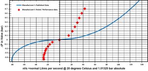
Fig. 1 Discrepancy between Manufacturers Published Data and 3rd Party Testing – The inaccuracy of the Published Intake figures is out by a factor of 4 and could put a pipeline under severe risk under Vacuum Conditions (Ref. S. García-Todolí, P. L. Iglesias-Rey, D. Mora-Meliá, F.J. Martínez-Solano, V. S. Fuertes-Miquel – Computational Determination of Air Valves Capacity 2018)
Myth 3 – Air Valve technology like other technologies evolve in a progressive way
Research into Air Valve design indicates that technologies evolve in interesting and convoluted ways and the misconception that design acceptance follows an evolutionary path of one successful design succeeding the next is not necessarily true as several air valve technologies run parallel to each other even though there may be substantial empirical data for one technology to supersede another. This peculiarity may exist due to several dynamic market forces and historical reasons.
Air Valve technology as it stands now indicates that even some of the more commercially successful designs are not superior from all points of view and have inherent limitations and that pedigree in age or popularity does not necessarily reflect pedigree in performance.
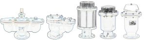
Fig. 2 The Evolution of Air Valves – The presence of all Air Valves technologies available simultaneously in the market and still widely specified is a very peculiar and interesting phenomenon. On the extreme left are Non-Kinetic Air Valves that suffer from premature closure on discharge developed more than 100 years ago and still in use around the world. On the left is a Kinetic Air Valves that can discharge Air at high creates but induce Waterhammer – developed more than 70 years ago and still in use. On the right are two Anti-Shock Air Valves designed to reduce Waterhammer in a limited range developed 30 years ago and still in use. On the extreme right is the AirFlo Variable Orifice Air Valves Designed to reduce Waterhammer across all operating conditions and to improve Vacuum protection Developed in 2010.
Myth 4 – An Air Valve equipped with a Surge damping device is guaranteed to protect a pipeline
The response to this myth is that it is highly dependant on whether the device is a pressure bearing component or not, whether the design has a static orifice or not and lastly whether the device has been activated before water enters the valve or not.
Most surge damping devices in air valves today, are based on a pressure bearing, static floating orifice, often termed an “Anti-Shock” or “Anti-Slam” orifice, that is activated based on the differential pressure across the large orifice.
If the Anti-Shock Orifice is activated at a very low differential pressure across the large orifice, then, the design may prevent Waterhammer but result in Surge (mass oscillation) which in the long term is as damaging to Plastic and GRP pipelines as Waterhammer. In addition, activating the device at low differential pressures increases the filling times of the pipeline substantially.
If the Anti-Shock Orifice is activated at too high a differential pressure, then it will induce Waterhammer. Research indicates that if the device is a pressure bearing component, then, it will be activated at a higher different differential pressure for higher working pressures and at a lower differential pressure lower working pressure for the same size. This is because, as a pressure bearing component, the mass of the device changes with the working pressure of the valve. In addition, research indicates that the so called “Switching Point” (the point at which this device is activated) differs for different size valves.
If the Anti-Shock Orifice is not activated at all then the valve will behave like a Kinetic Air Valve and induce Waterhammer on closure. There are several reasons why the device may not be activated. The most common reason is sizing too many air valves on a pipeline, a problem that is common when the Design Engineer uses the manufacturers air valve sizing and design software indiscriminately. Another reason is when the air valve has been sized only on the vacuum function and not looking at the overall function of the air valve across the operating cycle of the pipeline. The last reason is that the Design Engineer may have decided to standardize on the valve size on a pipeline to minimize future maintenance problems. Often when this occurs, the engineer will standardize on the largest valve sized on the pipeline. This implies that some air valves may be oversized for discharge. In these cases, the differential pressure may not be high enough across the large orifice to activate the Surge damping device thereby still creating Waterhammer on closure of the air valve.
The REXUS series AirFlo Variable Orifice design was developed to prevent the problems associated with conventional air valve with Surge Damping device. This patented design has a non-pressure bearing, adjustable floating orifice (Variable Orifice) that, automatically adjusts the outlet of the air valve in accordance with the velocity within the pipeline thereby assuring surge protection regardless of the flow rate within the pipeline. Test results indicate substantially better Surge protection than so called Anti-Shock designs under equal operating conditions.
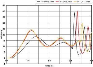
Fig. 3 The Sensitivity in Performance of the “Anti-Shock” Orifice – A DN25 Anti-Shock Orifice Response Time Testing – The graph indicates the results of the same valve with 3 different Anti-Shock Floats with one millimetre size difference between each size. The slight difference in weight and size impacts the valve’s responsiveness to Waterhammer dramatically (Ref. Dr. H. Warda and IH Adam – 2013 Conference Paper – Switching Criteria of Three Stage Air Valves).
4 Certainties about AirFlo Variable Orifice Air Valves
- AirFlo has been 3rd Party tested across its entire range. Published information can therefore be confidently referenced.
- AirFlo, because of its patented Variable Orifice design, provides superior Surge Protection in comparison to other air valves.
- AirFlo Variable Orifice Air Valves provides higher air intake capacities than conventional air valves. The reasons are because of its deliberate flow path design and that the Variable Orifice is a pressure bearing device.
- AirFlo Variable Orifice Air Valves are guaranteed to perform at the point of application. This design has worked under some of the most demanding applications including pipelines in diameters of up to 3.5 metres where, the pipelines’ sole Surge and Waterhammer protection is the Variable Orifice.
Allistair Balutto (c)